1.Introducing Glise
Glise is a subdivision surface modeler.
A modeler is a software aimed at shaping 3D objects using basic components like vertices, edges and faces.
A 'subdivision surface modeler' is a modeler specifically designed to let the artist work with subdivision surfaces in a natural and responsive way.
1.1.Subdivision
As the name implies, a subdivision surface is the result of a surface being somehow subdivided.
Basically a base mesh is subdivided one or more times, and the result is a subdivision surface. Such surface is much smoother, but also much more complex, than its base mesh. The more a base mesh is subdivided, the more the resulting subdivision surface becomes smooth and complex, increasingly approximating the ideal limit surface that can be generated by its base mesh.
The big advantage in using subdivision surfaces is that you can shape very complex objects by modeling much simpler base meshes. Just remember that you can only model a base mesh, its derived surface is generated automatically.
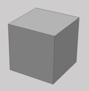
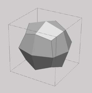
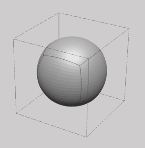
What you see above is a simple cube getting subdivided using 'Finer/Coarser' (see next session). After each subdivision step the subdivision level of the cube increases, and its subdivision surface gets smoother.
Glise handles subdivision surfaces natively, which means that you can see in real time how a subdivision surface changes when you tweak or modify its base mesh, as in the pictures below:
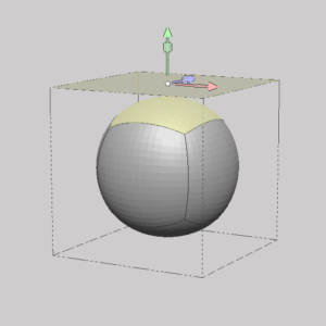
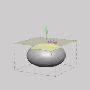
Note how by simply translating a single face of a cube subdivided 4 times you are actually tweaking 1536 polygons.
Remember that, unlike other 3D modeling packages, in Glise you are always working with two entangled entities: a base mesh (which you tweak and model), and its derived subdivision surface (which is automatically generated and managed).
When you use 'Finer/Coarser' (see next section) you are actually increasing/decreasing the display level (accuracy) of the generated subdivision surface, while the base mesh (which you model) remains unaffected.
1.2.Finer & Coarser
You can increase/decrease the subdivision level of a base mesh (that is, subdivide or unsubdivide a base mesh) with
Edit → Display → Finer/Coarser
These operations will modify the current subdivision level of any base mesh with one or more components selected. If there is no selection available, every base mesh in the scene will be affected.
1.3.Refine
You have seen how tweaking a single face in a base mesh may affect thousands of individual polygons in its subdivision surface. Now suppose you need a spike in the middle of your subdivision surface: if you are working with a simple cube, you just can't have that spike. There are simply not enough components to let you work only on a small part of your subdivision surface without altering the rest of it. What you want to do in this case is add more components to your cube so that you will have more elements to work with.
By adding more components to your base mesh you will be able to model your subdivision surface with a much more localized control.
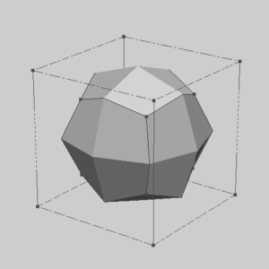
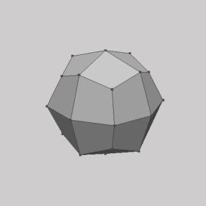
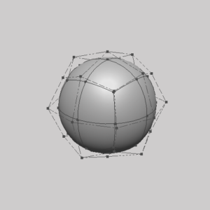
On the left: a base mesh with a single level of subdivision. In the middle: the mesh is refined. On the right: the new, refined mesh is subdivided.
As you can see the new base mesh has way more components (vertices, edges and faces) you can work with, so that applying more localized modifications becomes extremely easy. Note also that by refining you are modifying only your base mesh.
The basic common modeling pipeline generally consists of several stages. The artist starts sketching the base rough shape of what she is modeling (usually starting from a cube or similar – hence the name 'box modeler'), setting the right size and proportions, then refining, adding details, then refining again, and so on. If you focus on the goals of the subdivision level you are working with, modeling becomes easier.
You can use
Popup Menu → Refineto swap a base mesh with its first level of subdivision.
2.The Interface
Glise features an uncluttered, minimalist interface.
2.1.Layouts, Viewports & Dialogs
A viewport is a container holding one of the following widgets:
Each widget is designed to perform a specific task.
Each viewport has a 'Viewport' menu you can use to change the widget contained in a viewport.
Layouts are predefined arrangements of one or more viewports. To change the current layout use
Edit → Interface → Layout
Viewports can also be contained into dialogs.
Edit → Interface → New Dialogwill open up to 4 extra dialogs, each containing a different viewport.
Dialogs can be freely moved and resized. To move a dialog, drag its upper bar or border. To close a dialog, click on the close widget located in its upper-right corner. To resize a dialog, drag the handle in its bottom-right corner.
Viewports dimensions can be changed by dragging the splitter handles between them, or if the viewport is contained in a dialog, by resizing the dialog itself.
In the following image, a 3-viewports layout with each viewport holding respectively a 3D Modeling Canvas, a Scene Manager and a Rendering Panel. Note the additional dialog holding a viewport with an orthographic modeling canvas.

Before exiting, Glise will store in its preferences file the current layout as well as any open dialog. This information will be used to make the workspace match the last configuration at startup.
2.2.Default Shortcuts
These are the default-assigned shortcuts.
| Action | Shortcut |
|---|---|
| frame camera to: left | Shift+1 |
| frame camera to: right | Shift+2 |
| frame camera to: top | Shift+3 |
| frame camera to: bottom | Shift+4 |
| frame camera to: front | Shift+5 |
| frame camera to: back | Shift+6 |
| camera: frame | Space |
| camera: frame all | Shift+Space |
| viewport display: hull | 1 |
| viewport display: combo | 2 |
| viewport display: subdivision | 3 |
| viewport display: xray | 5 |
| viewport display: flat | 6 |
| viewport display: smooth | 7 |
| file: new | Ctrl+N |
| file: save | Ctrl+S |
| file: quit | Ctrl+Q |
| toggle: viewport wireframes | 4 |
| toggle: viewport perspective | P |
| toggle: softselection | Ctrl+Shift+S |
| toggle: sketches | Alt+V |
| toggle: symmetry | Alt+S |
| toggle: local pivot | L |
| toggle: handles | E |
| toggle: gradient backgrounds | Alt+B |
| selection type: points | A |
| selection type: edges | S |
| selection type: faces | D |
| selection type: objects | F |
| selection type: multi | G |
| selection mode: paint | 8 |
| selection mode: area | 9 |
| selection mode: lasso | 0 |
| convert selection to: points | Shift+A |
| convert selection to: edges | Shift+S |
| convert selection to: faces | Shift+D |
| selection: invert | I |
| selection: select symmetric | Ctrl+Alt+S |
| selection: select loop | Q |
| selection: select ring | R |
| selection: select element | Ctrl+Alt+E |
| selection: grow | ArrowUp |
| selection: shrink | ArrowDown |
| selection: delete | Del |
| visibility: hide selected | H |
| visibility: show hidden | Shift+H |
| subdivision: finer | PgUp |
| subdivision: coarser | PgDown |
| undo-redo: undo modeling | Ctrl+Z |
| undo-redo: redo modeling | Ctrl+Y |
| undo-redo: undo selection | Alt+Z |
| undo-redo: redo selection | Alt+Y |
| handle orientation: world | Shift+7 |
| handle orientation: normal | Shift+8 |
| handle orientation: custom | Shift+9 |
| symmetry: calculate on X | Ctrl+Alt+X |
| symmetry: calculate on Y | Ctrl+Alt+Y |
| symmetry: calculate on Z | Ctrl+Alt+Z |
| symmetry: calculate from edges | Alt+C |
| layout: split none | Ctrl+1 |
| layout: split horizontal | Ctrl+2 |
| layout: split vertical | Ctrl+3 |
| layout: split horizontal+vertical bottom | Ctrl+4 |
| layout: split horizontal+vertical top | Ctrl+5 |
| layout: split vertical+horizontal right | Ctrl+6 |
| layout: split vertical+horizontal left | Ctrl+7 |
| layout: split horizontal+vertical | Ctrl+8 |
| viewport content: 3D modeling canvas | Ctrl+Shift+1 |
| viewport content: scene manager | Ctrl+Shift+2 |
| viewport content: python console | Ctrl+Shift+3 |
| viewport content: rendering panel | Ctrl+Shift+4 |
| new dialog: viewport [4] | Ctrl+Alt+4 |
| new dialog: viewport [5] | Ctrl+Alt+5 |
| new dialog: viewport [6] | Ctrl+Alt+6 |
| new dialog: viewport [7] | Ctrl+Alt+7 |
| tools: extrude selection faces | X |
| tools: extrude selection border edges | Shift+X |
| tools: extrude selection vertices | Ctrl+X |
| tools: bevel selection vertices | Ctrl+B |
| tools: cut faces/split edges/connect vertices/insert loops | C |
| tools: merge vertices | Z |
| tools: bridge faces | V |
| tools: refine | Shift+PgUp |
2.3.Custom Shortcuts
Shortcuts are composed of a single letter/number, arrow key, page up/down key or space, possibly with a combination of the following modifiers: Shift, Alt and Ctrl.
You can assign a custom shortcut to any menu item simply by pressing the desired key combination while the item is highlighted. If the desired shortcut has already been assigned to a different item, an overwrite confirmation dialog is shown. To remove an existing shortcut, use the Backspace key.
Custom shortcuts are automatically saved in the preferences file upon program termination, and loaded at startup.
3.Modeling
Glise holds a single scene. Using a 3D Modeling Canvas you can navigate through the scene and interact with the objects within.
Glise keeps track of the current canvas (that is, the 3D Modeling Canvas currently interacting with the user), and automatically directs any modeling shortcut to the appropriate viewport.
Each canvas shares a common popup menu. This menu holds every modeling tool, as well as a 'Viewport' submenu which is relevant to (and only applies to) the current canvas. Use a right mouse button click in a 3D Modeling Canvas to make the popup menu appear.
3.2.Display
Each canvas supports the following view modes:
- Hull - show only base meshes
- Combo - show both base meshes and subdivision surfaces
- Subdiv - show only subdivision surfaces
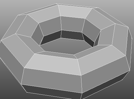
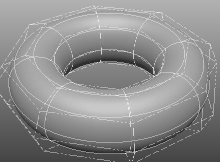
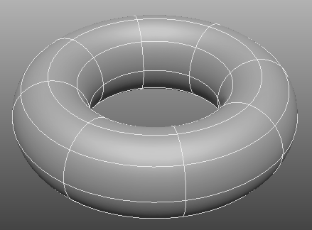
In the pictures above, the same canvas in different view modes (Hull on the left, Combo in the middle, Subdiv on the right).
You can change the view mode of the current canvas using
Popup Menu → Viewport → View
As you can see in the following pictures, there are two indicators in the bottom-left corner of each canvas, showing its current view mode and the perspective/orthographic setting of its camera.
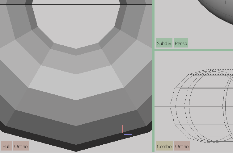
Each canvas can use different shading modes:
- X-Ray
- Flat
- Smooth
In the following pictures, from left to right: X-Ray, Flat, Smooth.
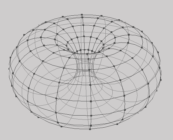
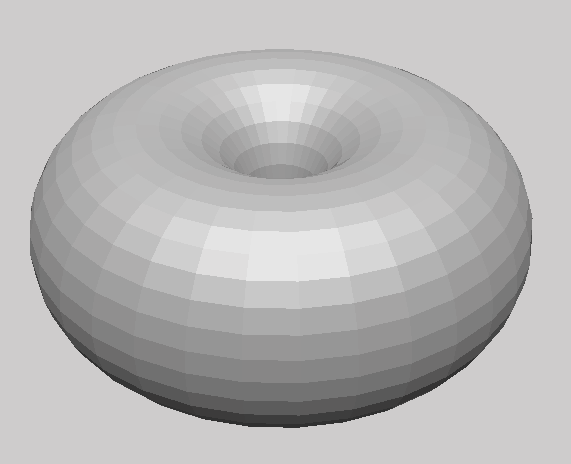
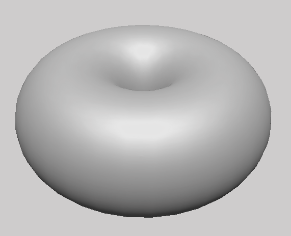
You can change the shading mode of the current canvas using
Popup Menu → Viewport → Shading
As you can see in the following pictures, each canvas can hide or show wireframes (on the right, wireframes are hidden).
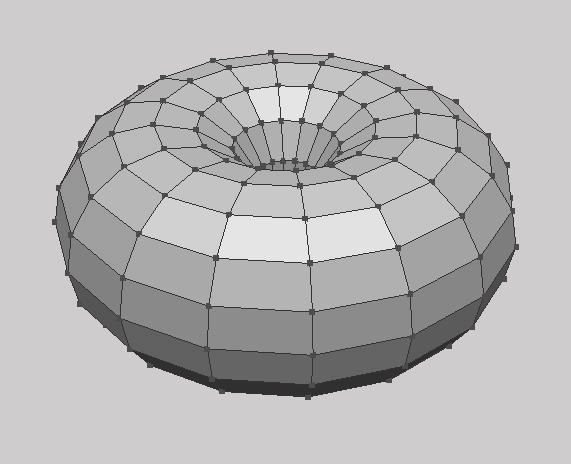
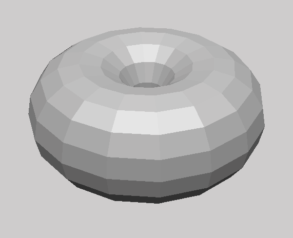
You can toggle the wireframe display of the current canvas using
Popup Menu → Viewport → Toggle Wireframe
Note that wireframes are always visible if the canvas is in X-Ray shading mode.
3.3.Preselection, Selection & Soft Selection
In order to perform the vast majority of modeling operations, there must be a valid selection or (more frequently) a preselection. When you move the mouse over an object, the underlying selectable component becomes preselected.
In the following pictures, a preselected face on the left (highlighted), and a selected face (with handles) on the right.
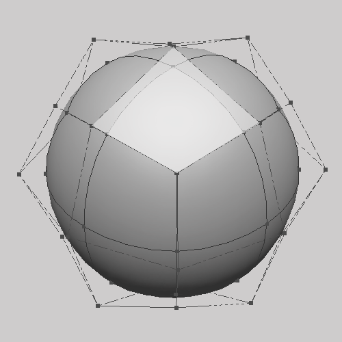
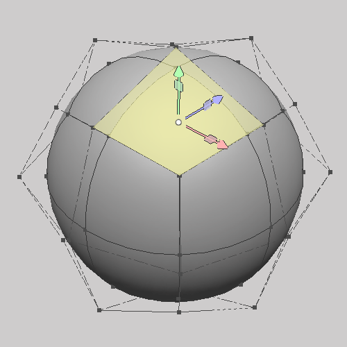
Clicking the left mouse button (LMB) on a preselection makes it the current selection.
If Ctrl is pressed, the preselected component is added to the current selection.
If Shift is pressed, the preselection is removed from the current selection.
An LMB click on an empty area clears the current selection.
The 'Selection' menu holds all the tools you need to manage selections.
Note that
Selection → Select Sideonly work with symmetry.
Selection → Select Symmetric
Also note that a LMB doubleclick on an edge will always perform a
Selection → Select Loopregardless of the current shortcut set for this function.
3.3.1.Selection Type
Selection → Typedefines what you can preselect/select/deselect.
It can be one of the following:
- Points
- Edges
- Faces
- Objects
- Multi
Note that 'Multi' is a combination of 'Points+Edges+Faces'.
3.3.2.Selection Mode
Selection → Modedefines how you can preselect/select/deselect.
It can be one of the following:
- Paint
- Area
- Lasso
In 'Paint' mode components can be selected in a brush-like way.
In 'Area' or 'Lasso' mode the user can draw a polygon with the LMB/middle mouse button (MMB) (either a rectangle in area mode or a free-form polygon in lasso mode) and everything inside the drawn area will be selected/deselected.
Drawing a selection polygon with the LMB restricts the operation to the visible components inside the area, while using the MMB will include any component inside the area, even if they are obscured by other components.
In the following pictures you can see the different selection obtained by drawing an area using the LMB (left) or MMB (right).
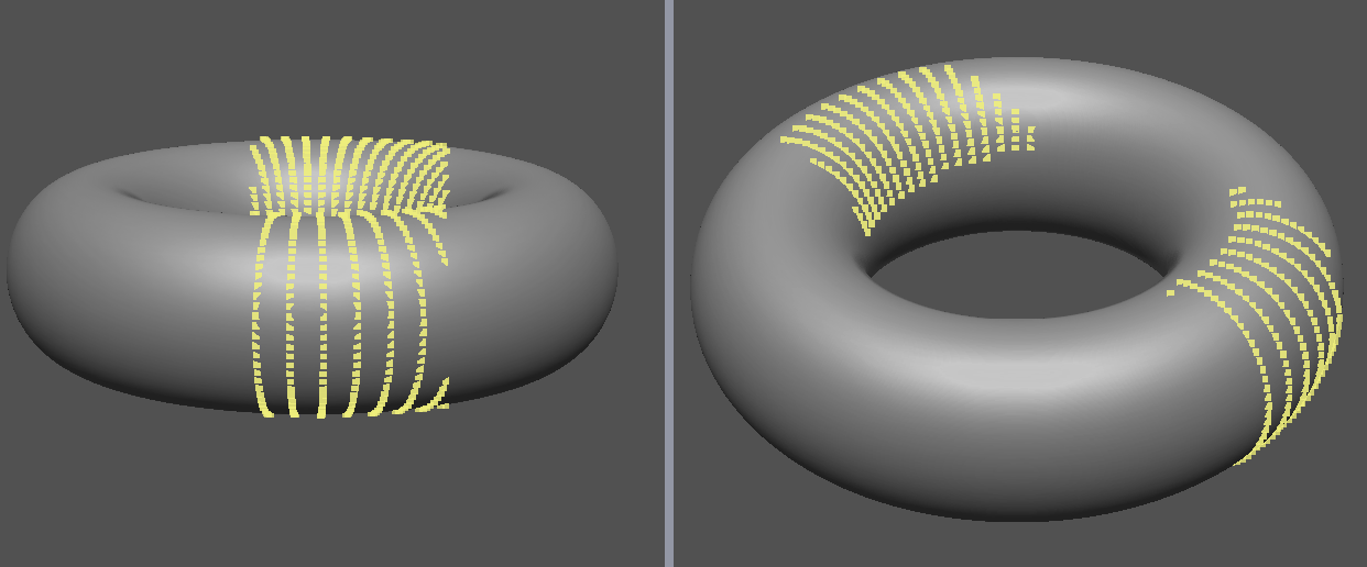
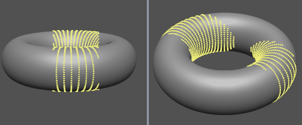
Note that single components can always be selected/deselected with an LMB click, regardless of the active selection mode.
3.3.3.Soft Selection
Soft Selection is a way to smoothly deform portions of a base mesh.
In the following pictures, tweaking with soft selection disabled (left), and enabled (right).
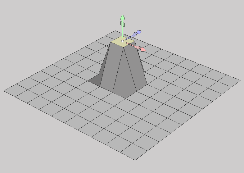
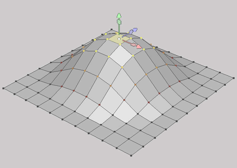
Soft Selection parameters can be modified using
Selection → Soft Selection
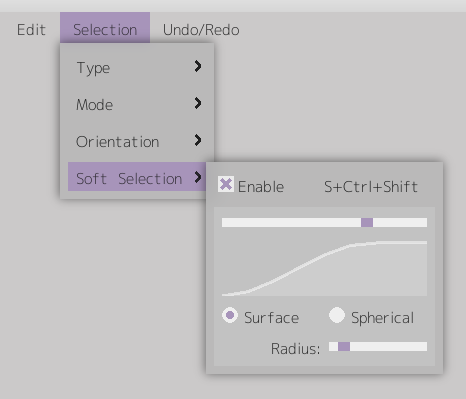
'Radius' defines the amplitude of the selected area, while the falloff, controlled by the main slider above the curve, describes how gradually the selection fades from full-selected (at the center of selection) to deselected (at the boundary). You can also control both falloff and radius by using the mousewheel while modeling: press Ctrl to modify the radius, Shift+Ctrl to modify the falloff.
When 'Surface' mode is selected, the selection will flow from the selection center up to the boundary defined by the radius, following every surface wrinkle and dent. If instead 'Spherical' mode is selected, the selection will be computed considering only the 3D distance of each vertex from the selection center, regardless of their actual connections.
Surface mode is slower to compute, but it correctly follows the topology of the surface.
3.3.4.Selection Undo/Redo
It is possible to walk backward and forward along the selection queue with
Edit → Undo Selection
Edit → Redo Selection
An undo/redo step in the selection queue will change the current selection to reflect the last valid recorded selection, along every other selection parameter (selection mode, selection type, handle position, etc.). Any selection will write to the selection queue at the position defined by the queue pointer at the time the selection was made. Going back to the middle of the selection queue, for instance, and performing a new selection, will truncate the queue and place the new selection in the last queue slot (the rest of the queue is lost). There is no limit to the number of slots available in the selection queue.
The selection queue is cleared each time a new session is started with
File → Newor a scene file is loaded.
3.4.Visibility
Any face of a mesh can be hidden, so that only a portion of it is displayed. As you can see from the pictures below, even if the artist is actually working on a whole body mesh (left) he/she can isolate a small part of it and focus on its modeling (right).
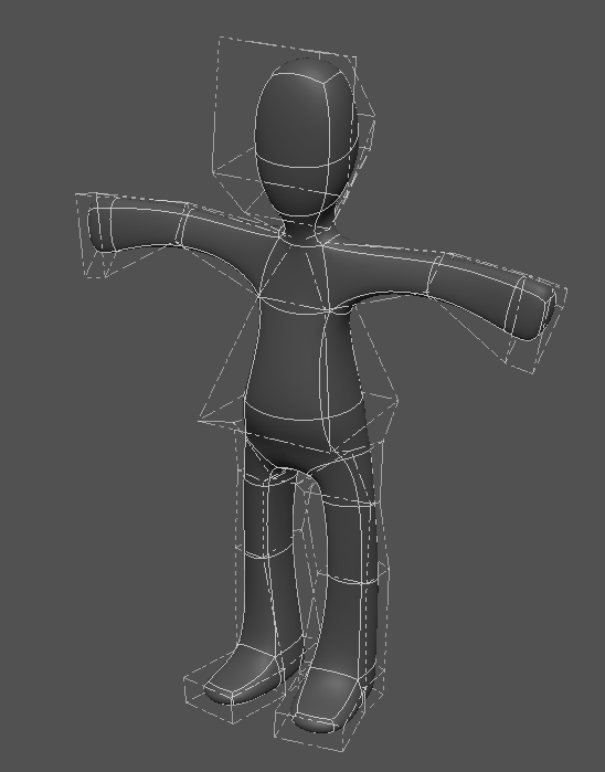
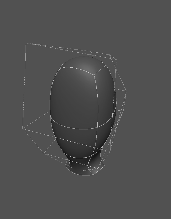
Use
Edit → Display → Hideto hide the current selection (any face shared by any selected component).
Use
Edit → Display → Show Hiddento restore the visibility of the whole scene.
3.5.Handles & Tweaking
A handle is a visual tool designed to manipulate the current selection.
As shown in the pictures below, the handle can be a Translate/Scale (left) handle, or a Rotate (right) handle.
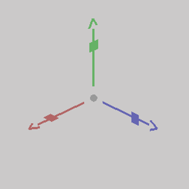
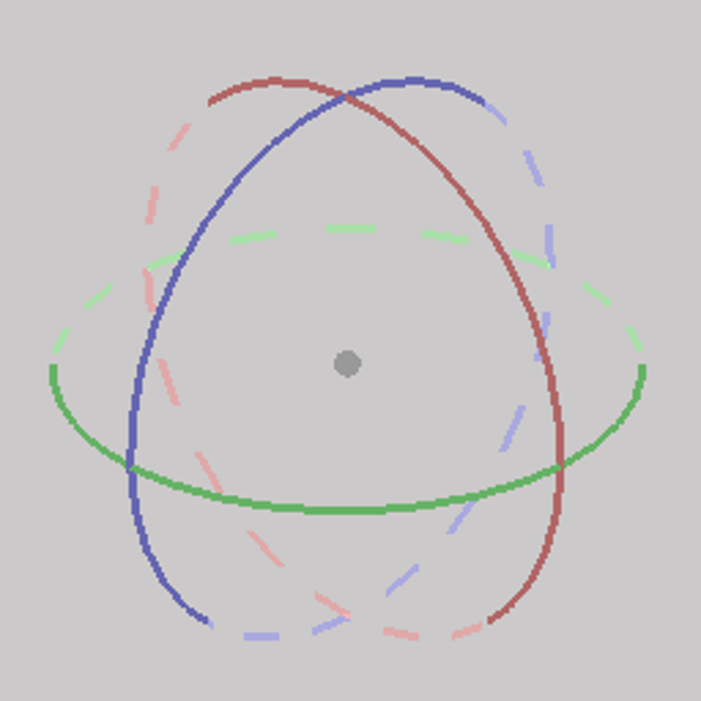
You can switch between the two handle types using
Edit → Toggle Handles
3.5.1.Translate/Scale Handle
Use the LMB to translate, the MMB to scale.
Dragging an axis with the LMB translates the selection on that axis only. Dragging the center with the LMB performs a translation on the plane currently front-aligned with the camera.
Dragging an axis with the MMB performs a scale operation on that axis only. Dragging the center with the MMB will uniformly scale the selection.
Holding down the Shift key while dragging an axis performs the requested operation on every axis except the selected one. Dragging one of the planes will restrict the relevant operation only on that particular plane.
3.5.2.Rotate Handle
Dragging a circle with the LMB rotates the selection around a specific axis.
Dragging the center (either with the LMB or MMB) rotates the selection in a view-dependent mode.
Holding down the Shift key while rotating locks the rotation at the closest multiple of 90 degrees relative to the initial angle of rotation.
3.5.3.Handle Position
The position of the handle is usually automatically calculated as the center of the current selection. However, the handle may be repositioned by holding down the Ctrl key while dragging a Translate/Scale handle. During this operation the handle will turn gray.
Repositioning the handle allows specific scale/rotate operations that depend on its position.
Note that the position of the handle will be reset when the selection changes.
3.5.4.Handle Orientation
Use
Selection → Orientationto choose the orientation mode of the handle.
It can be on of the following:
- World
- Normal
- Custom
In 'World' mode the handle's 'up' will always be aligned to the scene 'up' vector.
In 'Normal' mode the handle's 'up' will coincide with the normal of the current selection.
In 'Custom' mode, the orientation of the handle is manually adjusted.
Very much like translating the handle defines a new handle position, rotating the handle defines a new handle custom orientation. To rotate the handle, hold down the Ctrl key and perform a rotation with a Rotate handle. During this operation the handle will turn gray.
Note that manually adjusting the handle orientation will automatically switch to 'Custom' orientation mode.
3.5.5.Tweak Mode
Tweak Mode allows for fast tweaking of any preselected component without requiring any selection at all.
Hold down Shift+Ctrl while preselecting a component. Dragging the mouse while pressing the LMB will freely translate any preselection, dragging while pressing the MMB will scale it.
Using Tweak Mode in combination with Soft Selection allows the artist to perform organic tweaking intuitively, reducing mouse interactions to a minimum.
Note that Tweak Mode is not available if the current selection type is set to 'Objects'.
3.5.6.Modeling Undo/Redo
It is possible to walk backward and forward along the modeling queue with
Edit → Undo
Edit → Redo
An undo/redo step in the modeling queue will restore the vertices positions and meshes topology as recorded in the last slot of the queue. Any tweaking or topology change will write to the modeling queue at the position defined by the queue pointer at the time the change was made. Going back to the middle of the queue, for instance, and performing a tweak or a topology change, will truncate the queue and place the change in the last queue slot (the rest of the queue is lost). There is no limit to the number of slots available in the modeling queue.
The modeling queue is cleared each time a new session is started with
File → Newor a scene file is loaded.
3.6.Symmetry
Glise supports topological symmetry. This means that it is possible to work on part of a symmetrical model and have each topological change or tweaking automatically reflected on its symmetrical counterpart, even if each side of the model has been posed in a non-symmetrical pose. Symmetry works by using symmetry maps, which can be generated either by selecting one or two edges, or by a choosing an initial world axis reference. The method used to calculate a symmetry map has no influence on how topological symmetry is applied to the model.
To calculate a symmetry map, select one or two edges and use
Edit → Symmetry → Compute From → Edges
If selecting a single edge, this must lie on the central isoline of a model (that is, on the line that separates the left side from the right side). If such isoline does not exists (as in the case of a simple cube), just select two edges lying on opposite sides of the same central face (that will result symmetrical to itself). Both cases are shown in the picture below.
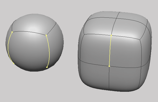
Alternatively, symmetry maps can be calculated relative to a world axis by selecting one or more meshes and using
Edit → Symmetry → Compute From → X/Y/Z Axis
You can enable or disable automatic symmetrical transformations checking or unchecking
Edit → Symmetry → Enable
Note that calculating a symmetry map automatically enables symmetry.
The current symmetry status is shown in the bottom-right corner of the main window.
When tweaking symmetrical models, Glise will automatically handle seams and cross-side selection overlappings.
Note that while models are allowed to be separated into elements (independent groups of faces), a symmetry map will always refer to a continuous surface, hence to a single element if more than one is present.
Symmetrical transformations on non-symmetrical elements belonging to a symmetrical model will be handled as if the model was non-symmetrical. A control mesh can have only a single symmetry map at a time, even if it is composed by more than one element.
3.7.Sketches
It is very common for artists to setup a reference frame using imageplanes (planes with images on them). Such reference is used to compare the work in progress with the actual images of the subject being modeled. This makes modeling way easier.
Glise provides an integrated reference system, called 'Sketches', which can be setup in a matter of seconds.
The 'Sketches' system is a reference frame implemented as an inverted-normal, textured cube with a dedicated drawing pipeline. It cannot be selected, nor deleted or referenced. Each side of the reference frame can be assigned a different image, and the opacity of the whole system can be dynamically adjusted.
As you can see in the following image, setting up the sketches is straightforward: use
Edit → Sketches → Enableto enable the sketches setup menu, and assign an image to at least one side.
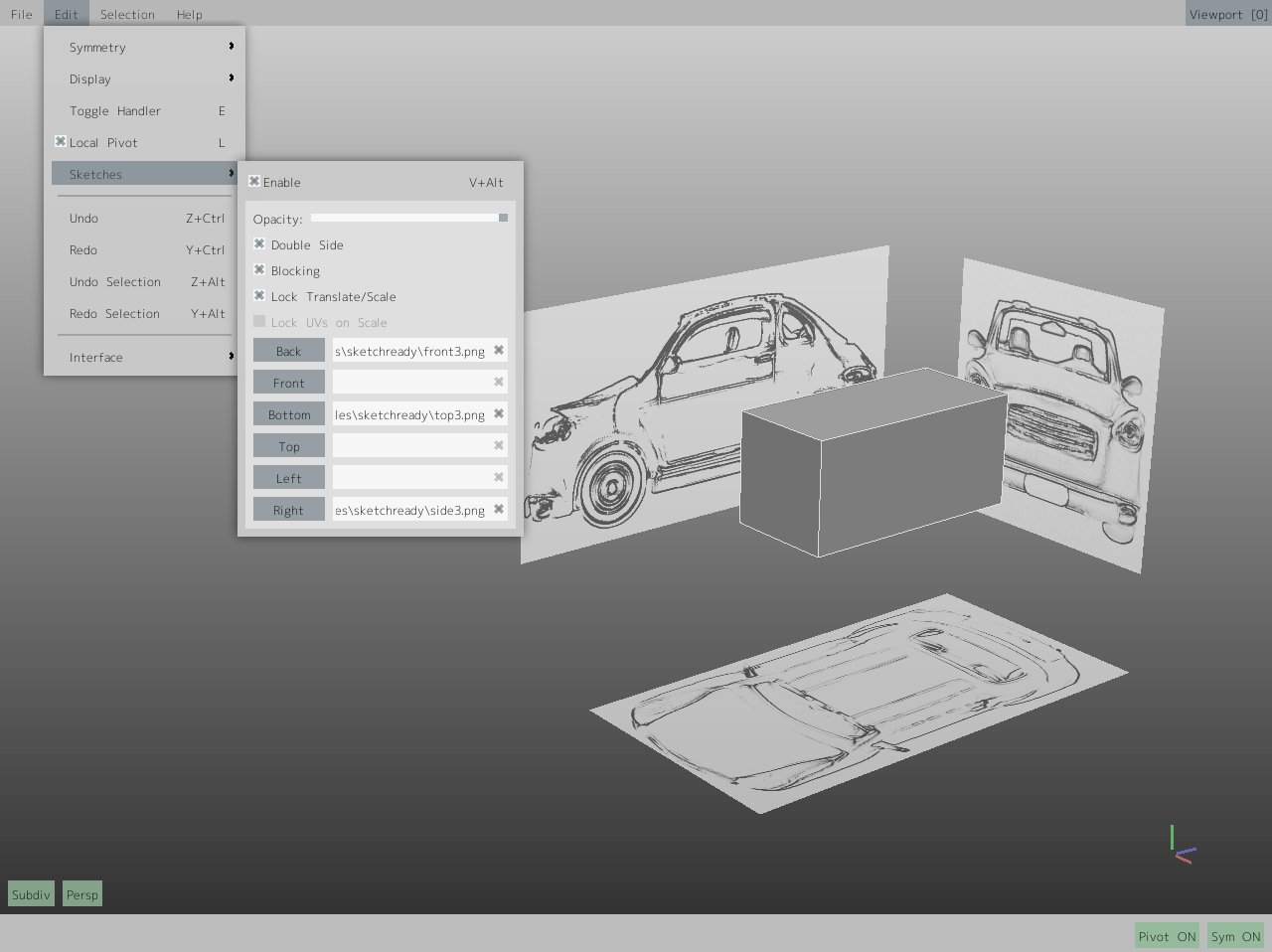
The proportions of the reference images are automatically calculated.
To remove a sketch just click on the cross widget to the right side of its image path.
It is possible to transform the sketches, so to make them translate or scale together with the objects being modeled.
When
Edit → Sketches → Lock Translate/Scaleis unchecked, each translation or uniform scale performed when 'Objects' selection type is active will also affect every sketch. In case of a uniform scale, if
Edit → Sketches → Lock UVs on Scaleis checked, the reference frame will be scaled, but the sketches will keep their size. This can be used to adjust the distance of the sketches from the models.
Note that the sketches in the reference frame are not allowed to intersect each other. Should this happen during a scale operation, the reference frame will lock on the smallest size it can have.
The reference frame is designed not to stand between the artist and his/her work. As such, each sketch is usually only visible when behind the meshes being modeled. However, sometimes it may be desirable to see a model through its sketch reference.
Check
Edit → Sketches → Double Sideto make each sketch visible even from its back.
By default sketches block any selection or preselection, regardless of their current level of opacity. This is useful, for instance, if a sketch is used as a middle plane from which only half mesh emerges, so that only half of a mesh can be selected. However, sometimes it is desirable to model through a sketch.
Uncheck
Edit → Sketches → Blockingto make sketches transparent to selection and tweaking.
Note that sketches are automatically included (by copy) in a GBE file.
4.Scene Management
Scene Management in Glise is pretty straightforward.
Everything is done using the Scene Manager, which is basically a table grouping few columns.
Using the Scene Manager it is possible to:
- Enable/disable single meshes
- Rename meshes
- Change meshes color
- Select/unselect meshes
- View mesh statistics
In the following picture you can see a Scene Manager showing the details of a scene holding only a cube and a torus.

The first column holds a checkbox, if it is unchecked then that mesh is disabled (in the image above, the torus is disabled).
Renaming a mesh is straightforward, just click on a name in the second column and an editor will let you modify the current line of text. Duplicate names are allowed.
The color swatch on the third column is an interactive widget, clicking on it will make a color picker dialog appear. Click the Ok button in the color picker to replace the current mesh color with the new, edited one.
To add/remove single meshes to/from the current selection, just click any place on the mesh line with none of the widgets discussed so far. You can tell if the mesh is selected because the whole record will have a yellow background.
For each base mesh, the last 3 columns show the total number of vertices, edges and faces. Note that these numbers refer to the base mesh (subdivision level 0). In addition, the faces column may also show a number between square brackets, this means that some of the faces of that mesh are hidden (in the image above, the cube has 3 hidden faces).
5.Rendering
Starting from version 1.6, Glise integrates a multithreaded, high-quality Ambient Occlusion renderer.
Ambient Occlusion is a rendering technique used to approximate Global Illumination. It does not need any light source or material, but provides a photorealistic-quality preview of the content of a 3D Modeling Canvas. It is often used by artists to check how an object will appear in a production rendering pass. You can launch your renderings from any Rendering Panel.
You start and fine-tune your renderings from the rendering popup menu (in the image below). Click with the right mouse button anywhere in a Rendering Panel and the rendering popup menu will appear.
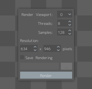
The Render Viewport is the index of the viewport holding the 3D Modeling Canvas you want to render. Each 3D Modeling Canvas shows its viewport index in its up-right corner. This combobox will allow you to choose only valid viewports. If there is no viewport currently holding a 3D Modeling Canvas, then the whole rendering popup menu will be disabled.
Threads refers to the number of parallel threads that will be launched to generate the rendering. More threads means a faster rendering. This field is set by default to the auto-detected CPU-core count, but it can be lowered to put less pressure on low-end systems. Direct control of hardware resources utilization can also be useful in case of multiple, concurrent renderings.
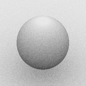
Samples directly affects the rendering quality. Use high sample count values for better quality, but significantly slower, renderings. Use low sample counts for quick previews. In the images below: 64 samples on the left, 128 samples in the middle, 256 samples on the right.
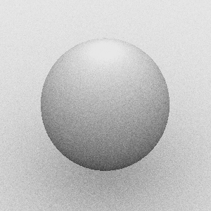
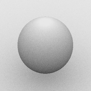
Resolution refers to the final rendering width and height, and it is set by default to match the current geometry of the Render Viewport. It can be changed to allow for lower/higher resolutions, which can be quite useful when the rendering is saved to disk, or when you just need a quick low resolution preview.
If Save Rendering is checked, the rendering will be saved upon completion. Use the ... pushbutton to choose the location and name of the final rendering image.
Push the Render pushbutton to start the rendering. A progressbar will constantly show the rendering status. Note that each individual rendering can be canceled anytime just by pressing the Cancel pushbutton.
Each rendering is performed in background, meanwhile you can continue to work with Glise as usual, even launching other renderings.
6.Programming
Glise comes with an integrated Python interpreter, and can be easily programmed using the Python language.
You can interact with the Python interpreter using the Pyton Console.
As you can see from the picture below, the console itself is pretty minimalist. One or more editors in the top input area, and a bottom scrollable output. The two sections can be dynamically resized by dragging the splitter handle between them. Click with the right mouse button anywhere in the input area to make the python console popup menu appear (it is visible in the image). Note that no custom shortcuts can be assigned to any item in this menu.
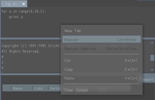
You can add more tabs (more editors) to the input area using New Tab in the python console popup menu.
As you can see in the image above, the python console popup menu also includes Cut/Copy/Paste operations, as well as execution or partial execution of the Python code in the active editor.
To know more about programming in Glise, please consult the Glise API Reference.


 Was this helpful?